There are seven basic methods used in the institutional setting for measuring ionizing radiation. The method selected depends on the type and amount of radiation to be measured, the requisite sensitivity, the time available for the measurement, and equipment cost.
Gas detectors
One of the oldest methods of measuring ionizing radiation is the gas detector. A simple design would be comprised of no more than an anode and cathode that define a volume in space, a voltage supply, and an ammeter. See Figure 1.7.
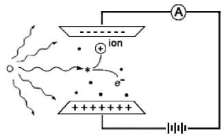
FIGURE 1.7 A SIMPLE GAS DETECTOR. A simple gas detector is comprised of an anode, cathode, voltage supply, and ammeter.
Characteristic curve
Gas detectors demonstrate a characteristic curve of signal strength as a function of applied voltage; see Figure 1.8. In all cases the signal is initiated when a photon or charged particle ionizes a gas molecule in the detector volume.
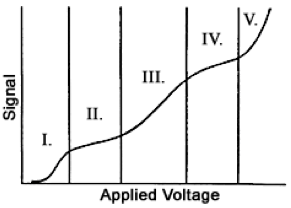
FIGURE 1.8 THE CHARACTERISTIC CURVE FOR GAS DETECTORS. The exact shape of this curve would be different for each detector design, but the five different regions would be observed. They are: I‐ recombination; II‐ionization; III‐ proportional; IV‐GM; and V‐continuous discharge.
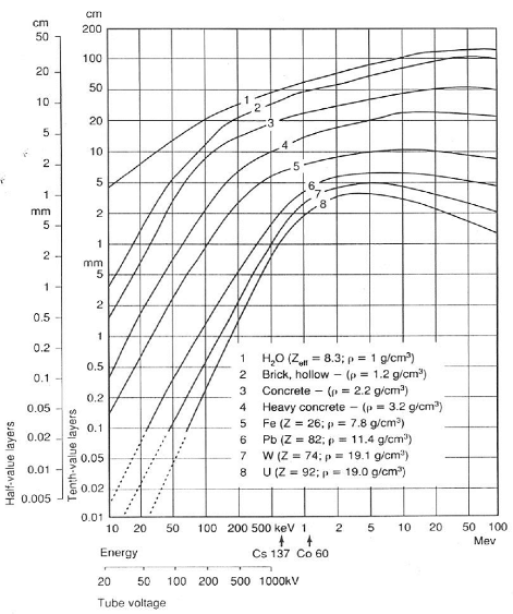
FIGURE 1.9 HALF VALUE LAYER FOR PHOTON ENERGIES FROM 10 KEV TO 100 MEV. SEE HANDBOOK OF HEALTH PHYSICS AND RADIOLOGICAL HEALTH CHAPTER 6.
Recombination
If the applied voltage is very low, after an ionization event, the negatively‐ charged electron and the positively‐charged ion will be electrostatically attracted to each other, and will recombine. There will be no signal from the detector.
Ionization
If the applied voltage is just sufficient to collect all the released electrons on the anode, and provide replacement electrons from the cathode, we observe a current that is proportional to the exposure rate. A gas detector operated in this mode is called an ionization chamber. Refer to Knoll ch. 5.
Ionization chamber survey meters are used to measure external radiation dose rate to individuals at levels of about 0.1 millirem per hour or greater. Their use at lower dose rates is limited due to the small electrical signal. The instrument can give false low readings if used to measure intense pinhole beams such as a leak from an x‐ray diffraction unit, or intense pulsed radiation, such as from an accelerator.
Small, electrically charged pocket ionization chambers are used to measure whole body dose for individuals who occasionally work in a radiation area, or who may be exposed to a high dose rate while performing a special task.
Roentgen, a measure of exposure
The ionization chamber in Figure 1.7 leads us to the first well‐defined unit of radiation exposure, the roentgen (R). The roentgen was originally defined as the amount of ionizing x‐ray exposure that would liberate 1 electrostatic unit of negative or positive charge per cubic centimeter of air. Now considered obsolete, it is approximately equivalent to a rad or a rem of radiation dose. Those units are discussed later.
Proportional counter
If the applied voltage is increased, rather than collecting an electrical current, each individual ionizing particle can cause a cascade of secondary ionizing events that are detected as an electrical pulse. The process is called gas multiplication. The magnitude of the electrical pulse is proportional to the energy of the particle that initiated the signal. Thus, for a fixed applied voltage, the signal from a 4.9 MeV 241Am alpha particle will be almost three times larger than the signal from a 1.8 MeV 32P beta particle. See Knoll ch. 6.
Proportional counters are commonly used for measuring environmental and laboratory contamination survey samples.
Geiger‐Mueller (GM) tubes
If the voltage is increased further, an individual particle can cause a complete ionization of the gas in the detector. Any ionizing particle, whether high or low energy, whether charged or uncharged, that interacts with the detector gas generates a large electrical pulse. A detector operated in this mode is called a Geiger‐Mueller, or GM detector. A GM instrument can become paralyzed and give a false‐low reading in continuous high dose rate fields or pulsed fields. See Knoll ch. 7.
GM tubes are commonly used as survey instrument detectors because the complete instrument is relatively inexpensive, lightweight, and rugged. Note that, although a GM survey instrument may have a “millirem per hour” exposure scale, the calibration is valid only for the radiation source used to calibrate the instrument, usually Cs‐137. Depending on the type of radiation encountered in the laboratory and its energy, this instrument may indicate low to five‐ or ten‐ fold high when used to measure dose rates. Thus, it must be calibrated for the radionuclide of interest if accurate measurements are needed.
GM survey meters are often used to conduct cursory contamination measurements. The meter indicates “counts per minute”; contamination action levels are expressed in “disintegrations per minute.” Because the GM detector is energy sensitive, readings must be corrected for the detection efficiency for the radionuclide of interest. Typical efficiencies are provided in Table 3.4.
Continuous discharge
If the voltage in the gas detector were increased further, the positive charge on the anode would pull electrons off the cathode and there would be a continuous signal whether ionizing radiation were present or not. This is referred to as continuous discharge. A detector operating in this region cannot be used as a measuring tool.
Film
The earliest radiation detector was photographic film. The unexpected darkening of photographic plates led Wilhelm Roentgen to the discovery of x‐ rays in 1895. An ionizing particle disrupts the silver bromide crystals in the film emulsion, allowing the silver to be precipitated onto the film substrate during processing. A greater radiation dose to an area of film results in a darker image.
Film is used for medical imaging; see Bushberg ch. 9 and 13. It is also used in film badge to measure personalwhole body dose. A small film sandwiched between metal and plastic filters in a plastic holder provides a personal monitor that can measure penetrating and non‐penetrating dose. See Figure 1.10. The amount of darkening under each filter sandwich is a function of dose. Only higher energy penetrating radiation will darken the film within the metal sandwich; beta dose will darken the film in the open window of the badge. See Cember ch. 9.
![]()
FIGURE 1.10 TYPICAL FILM BADGE. The film badge is comprised of a plastic holder, metal filters, and a film packet with slow and fast emulsions.
Thermo‐ luminescent dosimeters (TLDs)
Some crystals, such as LiF, store ionizing radiation energy when valence electrons are moved to higher energy “traps” within the crystal matrix. The trapped electrons are released by heating the crystal. When they return to the lower valence energy level, the difference in energy is released as visible light. The amount of visible light released is proportional to the radiation dose absorbed by the crystal. The process is called thermoluminescent dosimetry.
TLDs can be used to measure patient dose in diagnostic radiology and radiation therapy. They are also used as extremity dosimeters to measure finger dose for individuals handling small, high activity sources or as a personal monitor.
Scintillation Counting
Some detectors convert a particle’s energy to visible light that can be measured with a photomultiplier tube (PMT). This is called scintillation counting. To measure non‐penetrating beta radiation, the sample is mixed with a liquid scintillant called a cocktail. To measure penetrating photon radiation, a solid state crystal detector is used. In either case, the charged particles, whether beta particles in liquid scintillation counting or the photoelectrons and compton electrons in x‐ray or gamma‐ray analysis, interact with the orbital electrons of the scintillator to create flashes of light. See Knoll ch. 8.
Liquid Scintillation counting (LSC)
To measure samples with beta emitters such as 3H, 14C, 35S, 32P, and 33P, the sample is added to a vial of liquid scintillation cocktail comprised of solvent and scintillant. The vial is then mechanically lowered into a light‐tight chamber that has two PMTs that detect the individual scintillation events.
NaI(Tl)
To measure samples with gamma emitters such as 125I or 99mTc, the sample can be placed beside a NaI(Tl) crystal that is optically coupled to a PMT; the entire assembly is enclosed in an aluminum envelope to keep out room light and humidity. The energy of the incident gamma ray is converted to a flash of light in the crystal. The PMT detects the individual scintillation events and their relative intensities.
“cpm” and “dpm”
Many types of radiation detection or measurement instruments indicate “counts per minute”; action levels are usually expressed in “disintegrations per minute.” Because all detectors are energy and geometry dependent, cpm readings must be corrected for the detection efficiency for the radionuclide of interest. Mathematically, dpm = cpm / efficiency. Typical efficiencies are provided in Table 3.4.